1-ENVIRONMENTAL CONDITIONS
1.1 |
Operation Temperature |
-40° C to + 90° C |
1.2 |
Storage Temperatur |
-40° C to + 100° C |
1.3 |
Relative Humidity |
10% to 95% |
2-ELECTRICAL SPECIFICATIONS
| 2.1 |
Input Voltage |
Min:2.5V Max:5.5V |
| 2.2 |
Power Consumption |
At 3.0 V |
Typ.: 9.0mA. Max: 15mA. |
| At 4.0 V |
Typ.: 11mA. Max: 15mA. |
3-MECHANICAL SPECIFICATIONS
| 3.1 |
Mounting |
Magnet mount. |
| 3.2 |
Horizontal Pulling Force of Magnet |
1.5 Kg Min. |
| 3.3 |
Shock |
10msec. Half sine wave. |
| 3.4 |
Vibration |
10~200Hz Log. Sweep 3.0G
sweep time: 15 Minutes, 3 Axes.
|
| 3.5 |
Magnet Threshold |
The antenna must stay atlached to the vehicle, at a speed of 180 km/h. |
| 3.6 |
Cable Pulling Off Force |
5-5- Min At room temperature Min 7Kg /10sec.Apply 7Kg /10sec pulling force between the cableand the antenna unit,no visible damage shall appear on the cable and connector. |
| 3.7 |
Bending Test |
After bending 908 right and left for 1,000 cycles, no permanent damage were found. |
| 3.8 |
Weight |
105g Max. |
| 3.9 |
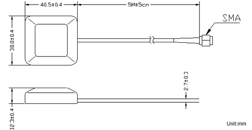
Dimension |
See Fig. 2 |
4.0 ANTENNA
| 4.1 |
Frequency Range |
1575.42 ¡Ó 1.023 MHz. |
| 4.2 |
Gain |
90° C: 5.0 dBi Min.
°C: -1.0 dBic Min.
Mounted on the 60mm*60mm ground plane. |
| 4.3 |
Polarization |
RHCP |
| 4.4 |
Axial Ratio |
.90° C: Typ 1.0dB
Mounted on the 60mm*60mm ground plane. |
5.0 LNA
| 5.1 |
Frequency Range |
1575.42 ¡Ó 1.023 MHz |
| 5.2 |
MMIC Gain |
27 dB Typ |
| 5.3 |
Noise Figure |
1.5 dB Max. ( +25° C ¡Ó °C)
1.8 dB Max. ( +85 ° C) |
| 5.4 |
Out Band Rejection |
fo = 1575.42MHz
fo ¡Ó 20 MHz 7dB MIN
fo ¡Ó 30 MHz 12dB MIN
fo ¡Ó 50 MHz 20dB MIN
fo ¡Ó 100 MHz 30dB MIN |
| 5.5 |
Output Impedance |
50 |
| 5.6 |
Output VSWR |
2.0 Max |
6.0 TOTAL SPECIFICATIONS (Through Antenna, LNA, Cable and Connector)
| 6.1 |
Frequency Range |
1575.42 ¡Ó 1.023MHz |
| 6.2 |
Gain |
At 90°C 31 ¡Ó 3dBi - (cable loss) Note:1 |
| mounted on the the 60mm*60m ground plane |
| 6.3 |
Output Impedance |
50 |
| 6.4 |
VSWR |
2.0 Max |
Note 1: Cable Loss = Max.( ¡V1.2dB / m)
7.0 OUTLINE

|