|
|
 |
|
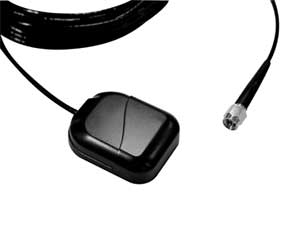
Stingray GPS antenna is the only innovating
design antenna with performance, quality and an RF protection circuit
built-in to protect the active LNA's, and most importantly the host GPS
receiver down the connector end from the danger level of high power RF
CW source exceeding over 1watt. The Stingray is a low
profile GPS active antenna system for the next generation multi-purpose
GPS mobile antenna products for Telematics, Fleet Management, Navigations
and AVL applications. This small print size of the antenna design does
not reflect over-all performance, since the antenna itself needs no ground
plane aid to deliver the L1 band small signal carrier that originates
from the 24 orbiting USA satellites located thousands of miles over-head
and with the ground reception power sensitivity at over -130dB. The Stingray
antenna is also design as a standard power input voltages in
range from +2.5Vdc to +12Vdc with reverse polarity shutdown, over-current
sense shutdown and an EMC power line suppression. The most important over-all
design concept of the Stingray active antenna is the
complete protections of the host sensitive GPS receiver made from any
manufacturer that it serve and can also be destroy or de-grade using an
improper design antenna.
|
| FEATURES |
|
 Narrow
bandwidth: <50 MHz Narrow
bandwidth: <50 MHz
Wide input power
supply voltage from +2.75V ~ +12V.
RG174 double shield
low loss, 2.7mm size.
Short-circuit protection
as standard design.
RF protection in
the front end
10 watt protection
(STR-1 only)
|
| |
|
|
| |
| STINGRAY(
STR-1 ) ANTENNA SPECIFICATIONS |
| General
|
|
2 Stages active LNA
|
|
|
|
BPF
|
|
|
|
RF protection(10watt) ,nano-second Spark-Gap (STR-1
ONLY)
|
|
|
Architecture Design
|
Dielectric Patch antenna
|
|
|
|
Low Noise Low drop-out, Linear Regulator
|
|
|
|
Low Loss RG/174 Coax cable with double shield
|
|
|
|
Aluminum Base/ PC+ Radome Plastic
|
| Performance
|
Receiving Frequency
|
L1 Band(1575.42MHz)
|
|
|
Output Impedance
|
50 ohms
|
|
|
Polarization's
|
Right Hand Circular (RHC)
|
|
|
Bandwidth
|
10dB MHz @ -3dB point
|
|
|
VSWR
|
1.5 Typical @ 1575MHz
|
|
|
Elev. Angle Coverage
|
5~90 degree
|
|
|
Az. Bearing Coverage
|
360 degree
|
|
|
Filtering
|
BPF <10 MHz B/W @-3dB
|
|
|
Over-all Gain
|
28dB (typical including 4dB cable loss & Filters)
|
|
|
Over-all NF
|
<1.8dB @fo, 2dB max.
|
|
|
LNA Characteristic
|
K=>1 Un-conditionally Stable
|
|
Electrical
|
Power Input
|
+2.75Vdc to + 12Vdc input, Auto Switching
|
|
|
Power Consumption
|
11mA to 13mA (max)
|
|
|
Power Input
|
Reverse Polarity Short Circuit shutdown
|
|
|
Over-Current
|
Thermal Over-current shutdown >+150degreeC
|
| Physical
|
Dimensions
|
44 x 34 x 12mm +/-0.5mm
|
|
|
Mount
|
Magnetic
|
|
|
Radome Color
|
Black
|
|
|
Coax Connector
|
BNC, SMA, SMB, MCX, MMCX, GT-5, Hirose-etc.
|
|
|
Coax Cable
|
RG-174U double shielded 5m, Low Loss 0.7dB/m
|
| Environmental
|
Operating emperature
|
-30 to + 85 degreeC
|
|
|
Storage
|
-40 to + 90 degreeC
|
| Option
|
OEM Hardware
|
1. Open Frame Antenna , with RF shield
|
|
|
|
2. Open Frame with 3?Flanges & RF shield
|
|
|
|
3. Ant + Aluminum Base
|
|
|
|
|