1. Hardware Specification
1.1 Technical Specification
- DGPS & SBAS (WAAS/EGNOS/MSAS)
- GPS L1( 1575.42MHz), C/A code
- 48 acquisition & 12 tracking channels
- Up to 60,000 simultaneous search windows
- Easy to integrate,
Dual UART data interface
Numerous GPIO
System specification
Typical receiver performance characteristics are presented in the following table.
General |
Receiver Architecture |
12 Parallel Channels, C/A L1(1575.42MHz) |
Sensitivity |
Autonomous Tracking |
-161dBm |
Time to Fix |
Outdoor: Cold / Warm / Hot |
35s / 32s / 3s typical |
Deep Indoor |
<20 s typical |
Accuracy |
Position |
2m CEP |
Velocity |
0.1 m/s |
Position-Indoor |
Far exceeds E911 requirements |
Interfaces |
Protocols |
? NMEA 0183 Ver3 |
1PPS Timing Output |
<20 ns resolution |
External Event Input |
<20 ns resolution |
Max Velocity / Altitude |
515 m/s 18,000m (increased rating version available subject to export license) |
Max Acceleration / Jerk |
4g / 1g /s |
DGPS and WAAS Capable |
? DGPS & SBAS (WAAS/EGNOS/MSAS) |
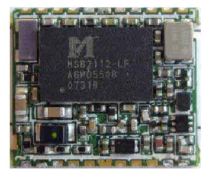
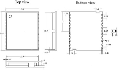
1.2 Physical Specification
- Size & Volume : 13(w) x 15(d) x 2.2(h)mm
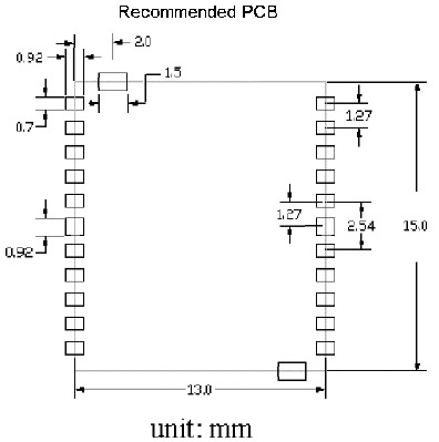
1.3 Recommend PCB Layout
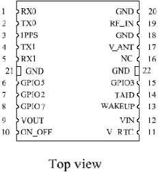
2. Module Pin Assignments and Description Table
Pin |
Name |
I/O |
Function |
1 |
RX0 |
Input |
Serial data input 0 (receive data) |
2 |
TX0 |
Output |
Serial data output 0 (transmit data) |
3 |
1PPS |
Output |
Synchronize with GPS time |
4 |
TX1 |
Output |
Serial data output 1 (transmit data) |
5 |
RX1 |
Input |
Serial data input 1(receive data) |
6 |
GPIO5 |
I/O |
General purpose I/O control pin (If no use, keep floating) |
7 |
GPIO2 |
I/O |
General purpose I/O control pin (If no use, keep floating) |
8 |
GPIO7 |
I/O |
General purpose I/O control pin (If no use, keep floating) |
9 |
VOUT |
Output |
Module power on indicate, 2.8V output |
10 |
ON_OFF |
Input |
Control module on/off, Low active (turn off module power supply) |
11 |
V_RTC |
Input |
RTC DC power input (input voltage 2.2~6V) |
12 |
VIN |
Input |
DC power (input voltage 3.2~5V) |
13 |
WAKEUP |
Input |
Wakeup GPS module from suspend mode (Low to wakeup and high to suspend) |
14 |
TAID |
Input |
AGPS mode support (Time Aiding from cell phone system) |
15 |
GPIO3 |
I/O |
General purpose I/O control pin (If no use, keep floating) |
16 |
NC |
N/A |
|
17 |
V_ANT |
Output |
2.8V RF power output for active antenna |
18 |
GND |
N/A |
Ground |
19 |
RF_IN |
Input |
GPS RF signal input |
20 |
GND |
N/A |
Ground |
21 |
GND |
N/A |
Ground |
22 |
GND |
N/A |
Ground |
(1) Ground pins
Pin18, 20, 21, 22 are module ground pins. Bigger ground planes and more ground vias around the pins isimportant to minimize the interference.
Pin SGND is for shielding ground. Connect these two pins together with other ground pins. Bigger ground planes and more ground vias around the pins is important to minimize the interference.
(2) RF input
The GPS module input is optimized to connect to a 50 ohm antenna. The minimized noise figure is achieved by -10dB input return loss. Well controlled antenna impedance (as close to 50ohm as possible) remains the stable system sensitivity. Do not try to match the GPS module to 50ohm for lower return loss which might induce the noise figure increased.
This is reserved for a non-50ohm antenna. For an application of 50ohm antenna,
The impedance of RF traces between GPS module, £k matching network, and antenna has be controlled in 50ohm +/-10%. The tight ground vias surround the RF traces is benefit to isolate noise out.
3) Active antenna DC power
The module has a built-in LNA, the applications for passive antenna performs well as active antenna with short RF traces between antenna and module (the path loss between the passive antenna and module induces the same degradation of system sensitivity directly).
(4) Power supply
3.2V ~ 5V is acceptable operation range of main power supply. The DC power ripple is required for less than 50mVpp.
(5) RTC power backup
2.2V ~ 6V is acceptable operation range of main power supply. The DC power ripple is required for less than 50mVpp.
3. Electrical Specifications
3.1. Absolute Maximum Ratings
Warning - Stressing the device beyond the "Absolute Maximum Ratings" may cause permanent damage. These are stress ratings only. Operation beyond "Operating conditions" is not recommended and extended exposure beyond the "Operating condition" may affect device reliability. This module is not protected against over voltage, reversed voltage or short current of RF_IN port.
Parameter |
Min |
Max |
Unit |
Power supply voltage(VCC) |
3.2 |
5.0 |
V |
Serial port input voltage |
-0.3 |
5.0 |
V |
BOOTSEL input voltage |
-0.3 |
3.6 |
V |
Storage temperature |
-40 |
125 |
°C |
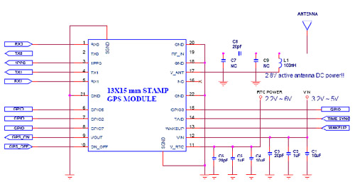
4. Application Schematics
5. NMEA-0183 Output Message
Its output signal level is TTL: 9600bps (default), 8 bit data, 1 stop bit and no parity. It supports NMEA-0183 V3.0
Protocol and the following
Messages: GGA, GSA, GSV and RMC.
The following is written assuming the user has a basic understanding of NMEA protocols and their use.
NMEA Output messages
| NMEA |
Record Description |
GGA |
Global positioning system fixed data |
GSA |
GNSS DOP and active satellites |
GSV |
GNSS satellites in view |
RMC |
Recommended minimum specific GNSS data |
|